
How SCADA Systems Actually Work: From a Wet-Well Sensor to an Operator Screen
Follow one remote wastewater lift-station signal from a 4–20 mA instrument through a ControlLogix PLC, Ignition Gateway, UDT, historian, alarms, and a high-performance Perspective application.

A SCADA screen is the visible end of a much longer engineering chain.
When an operator sees Wet Well Level: 7.8 ft, that number has already traveled through an instrument, field wiring, an analog input module, PLC logic, an industrial Ethernet network, an OPC driver, an Ignition tag model, and a Perspective binding. Along the way, every layer has made decisions about scaling, quality, alarming, history, security, and what the operator is allowed to control.
To make that chain concrete, we will follow a real-world teaching architecture for a neighborhood wastewater lift station containing:
- Two submersible pumps, P-101 and P-102, arranged as lead and standby/lag;
- One continuous wet-well level transmitter;
- An independent high-high level float;
- A magnetic discharge flow meter and force-main pressure transmitter;
- Two variable-frequency drives (VFDs);
- Building temperature, intrusion, utility power, UPS, and generator signals;
- An Allen-Bradley ControlLogix 5590-family controller;
- An Inductive Automation Ignition Gateway serving a Perspective application.
Note: This is a teaching architecture, not a construction standard. Actual instruments, setpoints, pump curves, electrical design, cybersecurity controls, and regulatory requirements must be engineered for each specific facility.
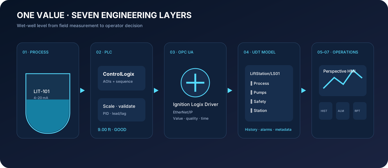
The Process Before the Pixels
Wastewater enters the wet well continuously. Under normal conditions, the PLC alternates which available pump is lead, balancing operating hours and starts.
Operations chooses a desired discharge-flow setpoint. When wet-well level rises above the start level, the lead pump starts. Its VFD ramps to a safe minimum speed, and a PLC PID loop adjusts speed to hold the flow setpoint. The pump continues until the wet well falls below the stop level.
This produces longer, steadier runs instead of repeated full-speed starts. But “run slowly for as long as possible” is not unconditional. Control must respect minimum continuous speed, motor cooling, ragging risk, force-main velocity, check-valve behavior, pump curves, and required drawdown time.
If inflow exceeds the lead pump’s capacity, or level reaches the lag-start elevation, the standby pump is called. With two pumps running, the program needs an engineered coordination strategy. A shared target, staged reference, or other hydraulic control may be appropriate; simply sending two VFDs the same PID output is not automatically stable.
The independent high-high float protects against failure of the continuous measurement. If the transmitter fails or becomes obstructed, the float can still initiate a critical alarm and, where the approved narrative permits, demand emergency pumping.
| Wet-Well Condition | Typical Automatic Response | | :--- | :--- | | Below stop level | Pumps stopped; lead retained or alternated after a cycle | | Start level reached | Start selected lead pump after proving permissives | | Pump running | Ramp above minimum speed and regulate discharge flow | | Level continues rising | Increase speed; call lag pump at engineered condition | | Stop level reached | Ramp down and stop after minimum-run constraints | | High-high float active | Critical alarm and approved fallback emergency sequence |
Key Takeaway: The PLC owns deterministic automatic control. Ignition supervises, records, visualizes, and permits authorized commands. Losing SCADA must never prevent essential local station control.
What is Installed at the Station?
A useful SCADA design exposes the process, equipment, and health of the control system, not just two pumps and a level number.
Process Instrumentation
| Instrument | Example Tag | Signal Type | Purpose |
| :--- | :--- | :--- | :--- |
| Hydrostatic or radar level transmitter | LIT_101 | 4–20 mA | Continuous wet-well level measurement |
| Independent high-high float | LSHH_101 | Discrete input | Backup hardwired overflow warning |
| Magnetic flow meter | FIT_101 | EtherNet/IP / 4–20 mA | Discharge flow and totalized volume |
| Force-main pressure transmitter | PIT_101 | 4–20 mA | Restriction, closed valve, line break, or head change |
| Building temperature transmitter | TIT_101 | 4–20 mA or discrete | Freeze risk and HVAC ventilation failure |
For each pump and VFD, a practical model commonly includes:
- Hand/Off/Auto or Local/Remote status;
- Available, ready, running, stopped, and faulted states;
- Start/stop command and command feedback confirmation;
- Speed reference and actual speed feedback (Hz / RPM);
- Motor current, power, voltage, and total runtime hours;
- Starts count and last-start timestamp;
- VFD warning and active fault codes;
- Seal-failure and motor-temperature thermal contacts;
- Commanded-versus-proven-running discrepancy alarms;
- Discharge-valve or check-valve limit switch status when instrumented.
Station-level telemetry points include utility power, generator run/fault, automatic transfer switch (ATS), UPS battery health, panel temperature, intrusion, wet-well flood switch, PLC CPU health, managed network switch port status, and radio/cellular communications signal quality.
Step 1: Turning Wet-Well Depth into 4–20 mA
Assume LIT-101 is calibrated for 0–15 ft:
4 mA  = 0.0 ft (Empty wet-well datum)
12 mA = 7.5 ft (Mid-level)
20 mA = 15.0 ft (Full range)
A current loop is well suited to industrial field wiring and provides a live zero: 4 mA is a valid zero measurement, while current dropping to 0 mA indicates an open circuit, broken wire, or instrument power failure.
In a common two-wire loop-powered arrangement, a 24 VDC supply powers the transmitter while the same series loop carries the measurement to a ControlLogix analog input module (such as a 1756-IF8I isolated analog card):
+24 VDC Supply ──> Transmitter (+)
Transmitter (–) ──> Analog Input Channel (+)
Analog Input Channel (–) ──> 0 VDC Return
The 1756-IF8I module converts continuous current into a raw digital value with 16-bit to 24-bit resolution and exposes channel diagnostic status bits. Underrange (under 3.6 mA), overrange (over 21 mA), and open-wire conditions become explicit quality faults.
Step 2: Making the Input Useful in ControlLogix
Inside Studio 5000 Logix Designer, the channel value is mapped into a consistent equipment structure. We utilize a custom analog-input Add-On Instruction (AOI) to:
- Acquire the raw analog integer and I/O health status;
- Scale endpoints into engineering units (feet);
- Clamp or flag implausible rates of change;
- Apply low-pass digital filtering where process noise warrants;
- Calculate process alarms with deadbands and on-delay timers;
- Provide maintenance override and simulation modes;
- Publish a standard UDT structure for SCADA consumption.
Engineering Value = (Input mA − 4) × (15 ft − 0 ft) / (20 mA − 4 mA)At 13.6 mA, the calculated level is 9.0 ft. A representative controller-scoped tag structure:
LS01.LIT_101.PV          9.00
LS01.LIT_101.EU          "ft"
LS01.LIT_101.Quality     192 (Good)
LS01.LIT_101.AlmHi       0
LS01.LIT_101.AlmHiHi     0
LS01.LIT_101.Fault       0
LS01.LIT_101.SimActive   0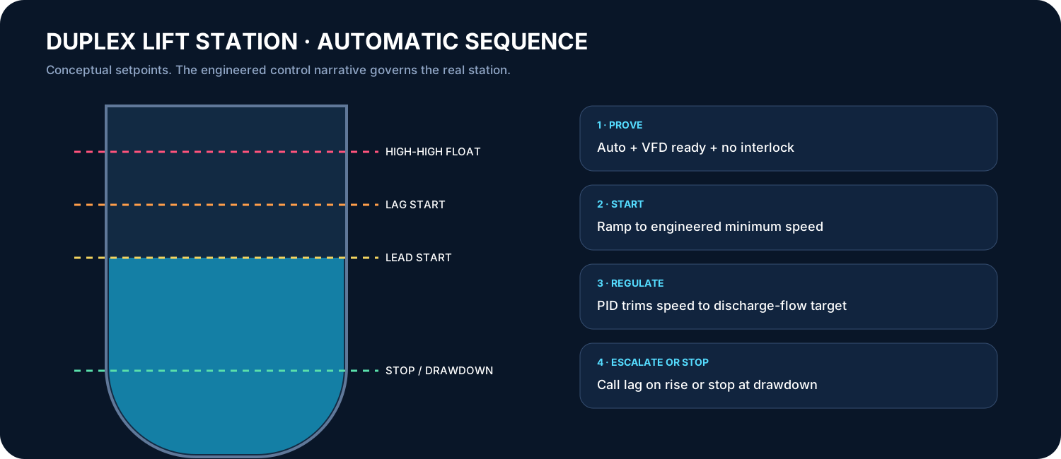
Before starting, the PLC verifies Auto mode, Remote selection, VFD ready status, healthy communications, no motor-temperature or seal faults, minimum wet-well level, no active emergency stops, and an open discharge path. The HMI faceplate should explicitly explain why a pump cannot start rather than merely disabling its Start button.
Step 3: From ControlLogix to the Ignition Gateway
The Ignition Gateway creates an Allen-Bradley Logix device connection. Ignition’s native Logix driver browses controller-scoped tags and communicates over EtherNet/IP (CIP protocol) using TCP port 44818.
An OPC tag in Ignition references a PLC member through an OPC item path:
[LiftStation_01]LS01.LIT_101.PVIgnition subscribes to values and adds timestamping and OPC quality metadata before making them available to Gateway services, alarm evaluation pipelines, and client sessions.
The operator is never looking directly into raw PLC memory registers. If the communication link drops, the HMI does not freeze at 9.0 ft and appear healthy. It immediately displays an unmistakable bad-quality overlay and comm-loss banner.
Step 4: Modeling the Station with Ignition UDTs
Copying loose tags for every lift station creates configuration drift. Ignition User Defined Types (UDTs) are reusable templates whose parameters dynamically resolve OPC paths:
[Wastewater]Lift_Stations/LS01
├── Process
│   ├── WetWellLevel       (AnalogInput UDT)
│   ├── DischargeFlow      (AnalogInput UDT)
│   ├── ForceMainPressure  (AnalogInput UDT)
│   └── BuildingTemp       (AnalogInput UDT)
├── Pumps
│   ├── P101               (PumpVFD UDT)
│   └── P102               (PumpVFD UDT)
├── Safety
│   ├── HighHighFloat
│   ├── FloodSwitch
│   └── Intrusion
└── Station
    ├── AutoMode
    ├── LeadPump
    ├── FlowSetpoint
    ├── PLCHeartbeat
    └── CommStatus
The PumpVFD UDT definition accepts {DeviceName} and {PLCPath} parameters. Instances point to LS01.P101 and LS01.P102 without duplicating a single line of tag configuration. Alarms, historian settings, engineering units, and display format strings are automatically inherited.
Step 5: Four Levels of High-Performance HMI
High-performance HMI design (ISA-101 standards) is not about dark themes and flashy animations. It is engineered to help operators rapidly detect, diagnose, and resolve abnormal situations. Normal equipment stays visually quiet; abnormal deviations immediately demand visual priority.
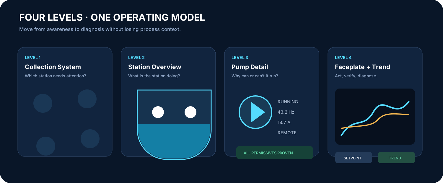
Level 1: Collection System Overview
A regional geographic map displaying all remote lift stations, force-main trunk lines, communications health, and highest active alarm priorities. A station with an active overflow risk stands out instantly.
Level 2: Station Overview
The primary operating screen displaying wet-well level with sparkline trends, discharge flow rate, force-main pressure, lead/lag pump selection, running status, high-high float state, utility power health, and active alarms. The station state is comprehensible in under three seconds.
Level 3: Equipment Detail
Selecting pump P-101 opens detailed diagnostics: command vs. feedback, start permissives checklist, active interlocks, VFD frequency/current/power, thermal status, runtime hours, start counters, and historical vibration trends.
Level 4: Faceplates, Trends, and Diagnostics
Popups support focused operational actions: adjusting an authorized flow setpoint, switching lead assignments, viewing multi-pen trend charts, acknowledging alarms, or reviewing VFD fault history. Every setpoint write requires role-based authentication and PLC-side range clamping.
Step 6: Historian, Alarming, and Remote Notification
The Tag Historian stores time-series data directly in SQL (PostgreSQL / TimescaleDB / Microsoft SQL Server).
A standard municipal alarm configuration includes:
- High and High-High wet-well level (Level 2 & Level 1 priority);
- Independent backup float tripped;
- Low-Low dry-run protection level;
- Commanded lead pump failed to start within 5.0 seconds;
- Both pumps unavailable (critical station failover risk);
- VFD trip or communications timeout;
- High force-main head pressure;
- Flow deviation while pumps commanded to run;
- Sub-freezing building temperature;
- Utility power failure, generator fault, ATS transfer, and cellular comm loss.
Ignition alarm pipelines route critical events through on-call rotation schedules using SMS, email, and voice dialer modules with escalation acknowledgment tracking.
Step 7: The Server Infrastructure Behind the Screen
In an enterprise municipal utility, services are distributed across high-availability virtual machines (Hyper-V / VMware / Nutanix):
- Redundant Identity Services: Single Sign-On (SSO) with MFA authentication;
- Back-End Ignition Gateways: Dedicated redundant I/O servers for PLC polling, history logging, and alarm evaluation;
- Front-End Ignition Gateways: Dedicated Perspective application web servers in a secure DMZ;
- Historian Cluster: Clustered time-series SQL database with automated off-site replication;
- Security Segmentation: Strict Purdue Model Layer 3 / Layer 3.5 DMZ isolation preventing direct internet access to the OT network.
What the Operator Finally Sees
When the operator opens Perspective on their console, they see Wet Well: 9.0 ft, P-101 running smoothly at 43 Hz, Discharge Flow at 620 gpm, P-102 ready in standby, and a clear green communication heartbeat.
Behind that simple, reliable screen:
- A field transmitter senses hydrostatic pressure;
- A 4–20 mA current loop delivers the signal through industrial noise;
- A ControlLogix AOI validates quality and scales engineering units;
- Deterministic PLC ladder logic regulates pump staging and VFD PID loops;
- Ignition's EtherNet/IP driver queries controller tags;
- Standardized UDT models attach metadata, historian logging, and alarm limits;
- High-performance Perspective components render clear operational context;
- Redundant server clusters and DMZ conduits secure the data end-to-end.
That is SCADA: not just pretty graphics on a monitor, but a complete, unbroken chain of trustworthy engineering from the physical process to the human operator.
References and Standards
- Inductive Automation: Connecting to Logix Drivers
- Inductive Automation: User Defined Types (UDTs)
- Inductive Automation: Perspective Architecture
- Rockwell Automation: ControlLogix 5590 Controller Specifications
- Rockwell Automation: 1756 Isolated Analog I/O User Manual
- ISA-101.01 Standard: Human Machine Interfaces for Process Automation Systems